Printing Practical Hardware: Designing Functional Parts in FreeCAD
Turn your Bambu Lab or Creality 3D printer from a toy factory into a functional manufacturing bench.
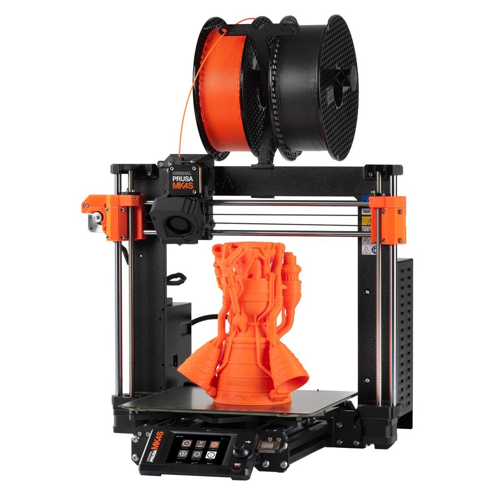
Most 3D printer owners spend their first three weeks printing plastic dragons and benchy boats before realizing their garage actually needs a dozen custom cable clips, replacement brackets, and sturdy wall mounts. If you want to move past the novelty phase, you need to step away from pre-made internet models and start drawing your own parts using parametric CAD.
Today we are looking at how to design custom functional hardware using FreeCAD and slice it properly for your Bambu Lab or Creality machine using engineering filaments like PETG and ASA instead of standard decorative plastics.
FreeCAD Part Design Workbench Basics
Designing mechanical parts means ditching sculpting software and embracing parametric modeling where dimensions are driven by math and constraints rather than freehand sketching. FreeCAD remains the go-to open source tool for this exact job, letting you define precise millimeters for mounting holes, countersunk screw seats, and snap-fit clips.
When you open FreeCAD, jump straight into the Part Design workbench. Create a new body, drop a sketch on the XY plane, and use the geometric constraint tools to lock down your lines. If you need a mounting bracket with a 5mm clearance hole for a machine screw, constrain that circle with an explicit diameter rather than eyeballing it on screen.
Filament Science: Choosing PLA, PETG, TPU, and ASA
Not all plastics behave the same way under mechanical stress or thermal loads. Standard PLA is stiff and easy to print, but it creeps under constant load and softens in a warm car during summer. For indoor brackets and general desk organization, PLA works fine, but structural parts demand better material choices.
PETG gives you higher impact resistance and temperature tolerance while remaining easy to print on an enclosed or open bed without toxic fumes. If you are printing vibration dampening feet or flexible clamps, grab a roll of 95A TPU. For anything going outside or inside a hot engine bay, switch straight to ASA, which resists UV degradation and high ambient temperatures far better than ABS.
Slicing Strategy: Wall Loops Over Infill Density
A common beginner mistake is setting infill density to 100 percent when trying to make a part unbreakable. That wastes time and filament while introducing internal stresses that cause warping. The secret to strong functional prints in Bambu Studio or OrcaSlicer lies in your wall loops, also known as perimeters.
Instead of bumping infill past 15 or 20 percent gyroid, increase your wall loops from the default two up to four or five. Most mechanical stress hits the outer skin of a printed part. Adding extra walls gives your screws more plastic to bite into and distributes shear forces evenly across the entire geometry.
How to Design and Print a Custom Hardware Mount From Scratch
What You Need Before Starting: FreeCAD installed on your PC, a Bambu Lab or Creality 3D printer, caliper measuring tool, and a roll of PETG filament.
- Step 1: Measure your target object using a digital caliper to capture exact mounting hole spacing, depth, and clearance requirements.
- Step 2: Open FreeCAD, select the Part Design workbench, create a new document, and start a new body and sketch on the appropriate plane.
- Step 3: Draw your base profile using lines and arcs, applying explicit dimensional constraints for every length, radius, and hole center.
- Step 4: Use the Pad tool to extrude your 2D sketch into a 3D solid object matching the exact thickness required for your hardware.
- Step 5: Export your finished model as a STEP file, import it into your slicer, set wall loops to 4, and print using PETG at manufacturer recommended temperatures.
Troubleshooting: What If Something Goes Wrong?
PROBLEM 1: Your FreeCAD sketch turns fully green or throws a redundant constraint error when trying to add dimensions.
THE FIX: Delete duplicate dimensions or conflicting geometric constraints until the solver states the sketch is fully constrained without over-defining it.
PROBLEM 2: PETG prints are stringing heavily and leaving rough blobs across the surface of your functional bracket.
THE FIX: Dry your PETG filament in a dedicated dehydrator at 65 degrees Celsius for six hours, and calibrate your retraction settings in your slicer.
PROBLEM 3: The printed mounting holes are too tight for your screws because of plastic shrinkage during cooling.
THE FIX: Offset hole diameters in your FreeCAD model by 0.3mm larger than the nominal screw size to account for thermal contraction during printing.
Original step-by-step tech guide & analysis by KejaniTech. Tried this guide or ran into a question? Drop a comment below!


Comments
Post a Comment